Why Cable Length Matters in Professional Audio Systems
How distance, signal type, and cable physics impact sound quality and system reliability
A signal that looks perfect on a workbench does not always behave the same way in a real building. Short patch cables hide problems. Long cable runs expose them.
On the bench, your cable may be three feet long and isolated from interference. In an installed system, that same signal might travel 100 feet through walls, ceilings, conduit, and equipment racks. Along the way, the cable interacts with its environment and with the signal itself. These interactions slowly shape, weaken, or contaminate the audio.
Understanding what happens over distance is what separates a system that works on day one from one that works every day.
The Physics of Long Cable Runs
As a cable gets longer, it becomes an electrical component rather than a simple connection. Three physical characteristics of the cable begin to influence the signal.
Capacitance (C)
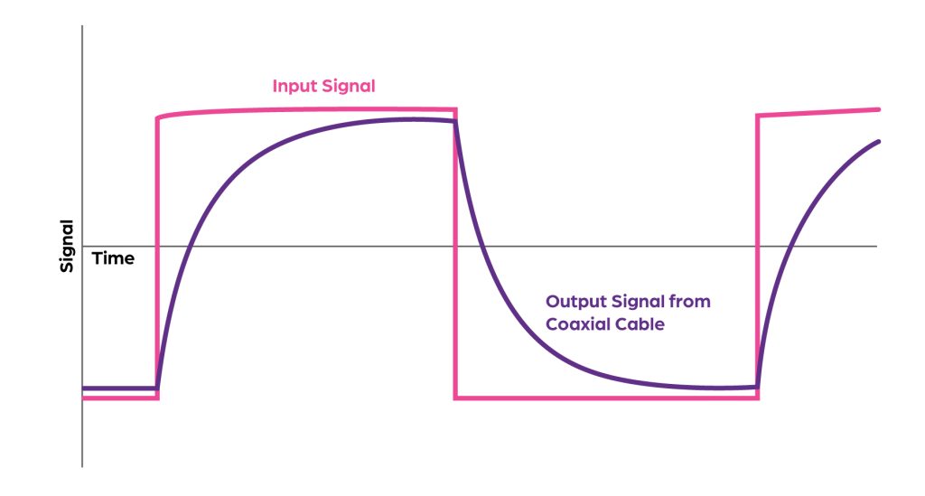
Capacitance is the cable’s tendency to store electrical energy between its conductors. Every inch of cable adds a small amount of capacitance. Over long distances, those small amounts add up.
In audio systems, capacitance acts like a low-pass filter. High frequencies are affected first, because they change more rapidly than low frequencies. As capacitance increases, high-frequency energy is shorted to ground. The result is audio that sounds dull, less detailed, or “closed in,” even though nothing appears broken.
This is why high-frequency loss is often the first sign that a cable run is too long or improperly specified.
Resistance (R) and Inductance (L)
Resistance is the opposition to current flow in the conductor. Longer cables have more resistance, which causes a reduction in signal level by the time the signal reaches its destination. In extreme cases, this can push signals closer to the noise floor. Stronger signals at the source can help overcome the resistance, but there are limits to how strong signals can be where they originate.
Inductance is created by the magnetic fields that form around conductors as current flows. Over long distances, inductance can cause subtle timing and phase issues. While these effects are usually small in audio frequencies, they become more noticeable as cable length increases or when paired with sensitive equipment.
Together, resistance and inductance reduce signal strength and accuracy over distance.
Noise Pickup and Crosstalk
A cable is not just carrying a signal. It is also exposed to everything around it. The longer the cable, the more opportunity it has to collect unwanted energy.
Lighting dimmers, motors, power cables, wireless devices, and networking equipment all generate electromagnetic and radio-frequency interference. Long cables act like antennas, especially if they are unbalanced, poorly shielded, or have a poor quality design.
This interference can manifest as hum, buzz, clicks, or intermittent noise that seems to come and go depending on what else in the building is operating, or can be constant based on environmental factors like nearby radio transmitters and cellular site.
Why Signal Type Matters
Not all signals are equally capable of surviving long distances. Understanding signal level and topology is critical to system design.
Microphone-Level Signals
Microphone signals operate at extremely low voltage, often measured in millivolts. Because they are so weak, any noise introduced along the cable can be comparable in level to the signal itself.
This makes mic-level runs especially sensitive to cable quality, length, shielding, and nearby interference. Long mic runs are common, but they must be balanced and carefully routed to avoid noise problems.
Line-Level Signals
Professional line-level signals operate at a higher voltage, typically +4 dBu or around 1~2 Volts RMS. This higher level provides better immunity to noise because the signal is much stronger relative to any interference picked up along the way.
Line-level signals can travel much farther than mic-level signals without degradation, making them better suited for longer analog runs.
Balanced Signals (XLR and TRS)
Balanced connections send the same signal on two conductors with opposite polarity. Any noise picked up along the cable affects both conductors equally, assuming good construction of the cable.
At the receiving end, the system subtracts one signal from the other. The original audio remains, while the noise cancels itself out. This process, called common-mode rejection, is the reason balanced connections are so effective in real-world environments.
Balanced cabling is the backbone of professional audio installations because it dramatically improves noise immunity over long distances.
Unbalanced Signals (RCA and Tip-Sleeve Phone Connectors)
Unbalanced connections carry signals on a single conductor referenced to ground. Any noise picked up along the cable is added directly to the signal.
Because there is no mechanism to cancel interference, unbalanced cables become unreliable over distance. In most environments, runs longer than 15 to 20 feet are likely to experience noise, hum, or high-frequency loss. Shielding in the cable can help prevent noise pickup, but effective shielding is typically limited by cable flexibility requirements.
Unbalanced signals should be kept short or converted to balanced as soon as possible.
Digital Audio Signals
Digital audio systems transmit data rather than continuous waveforms. This makes them resistant to low-level noise that would affect analog audio.
However, digital systems operate on thresholds. As long as the signal is strong enough and timing remains accurate enough to receive, the audio is perfect. Once errors exceed the system’s ability to correct them, the audio drops out entirely.
This behavior is known as the digital cliff. Instead of gradual degradation, digital failures are sudden and disruptive, often presenting as silence, clicks, or loss of synchronization.
How Cable Problems Show Up in the Field
When cable physics are ignored, the symptoms are usually consistent:
Loss of clarity or signal strength caused by excessive capacitance and resistance.
Hum or crackling tied to power systems or building equipment or environmental noise.
Digital dropouts caused by timing errors, jitter, or signal loss.
These issues can be difficult to diagnose because they often appear only under certain conditions or after installation has been completed.
Practical Design Guidelines
A few design decisions can prevent most cable-related problems:
Balance early. Convert unbalanced sources to balanced signals as close to the source as possible.
Shorten analog paths. Place preamps, processors, or A/D converters closer to microphones and instruments.
Respect power infrastructure. Keep audio cables away from power lines and transformers. Cross at right angles when necessary. Run analog cabling inside of steel conduits that are grounded.
Test worst-case runs. Always test the longest cable paths, not just the average ones.
Avoid unnecessary length. Extra cable adds capacitance and reistance, even when coiled and unused.
Designing for Reliability
Cables are not passive bystanders in an audio system. Over distance, they shape the signal in measurable and audible ways.
By understanding how resistance, capacitance, inductance, and noise interact with different signal types, designers can move beyond assumptions based on short test cables and build systems that perform reliably in real-world installations.